Electronics Basics
For those of you who want to experiment with high voltage, but have no knowledge of it whatsoever, this is the place to be. I will go through some very basic stuff to get you started including electricity in a nutshell, electronic components and what they do, and also a quick guide on how to solder and desolder.
Electricity in a nutshell (and all of its cool terms)
When we hear the word electricty, we often think of big blue arcs or lighting. What we don't think of is what electricity really is. By deffinition (in my simple form), electricity is the flow of an electrical charge through a conductor. The flow is caused by the attraction of different particles, and repulsion of same particles (like with magnets). An electric charge is basically an excess (positive charge) or deficiency (negative charge) of electrons. If you want to go deeper than that, you'll have to research it on your own. This guide is just for the basics.
There are also some basic terms that apply to electricity that I will go over so you know what I'm talking about as you read it.
Coulomb: A Coulomb is basically a quantity of electricity. It is defined as the ammount of charge that moves through a conductor in one second if the current is one amp.
Ampere: The simplest way to define an ampere is just that it's used to measure the ammount of electrical current moving through a conductor. It's usually shortened to 'amp' and abbreviated to 'A'. Most of the work we do will be less than one amp, so we start using milliamps, which is abbreviated to mA. There are 1000mA in one amp. I'm sure most everyone has heard the old saying "It's not the volts that kill you, it's the amps". However thats not all there is to it, the amps are tied into the volts quite a bit, however before I get into that I'll go into what can kill you. Basically just go by the 1-10-100 rule. This is "1 milliamp can be felt, 10 milliamps causes muscle paralysis, and 100 milliamps will stop your heart". This is completely true but your skin is a very good resistor. On me I got ratings of 650,000 ohms to 750,000 ohms from left hand to right hand with dry skin. However, when I wet my hands down with tap water (to make them more conductive) I only had a resistance between 60,000 and 220,000 ohms. So you can see why grabbing the mains voltage wont kill you normally, but could if you were say in the shower/ bathtub.
Volt: The difference in electrical potential between two conductors with one amp of current when the power dissipated between the two conductors is one watt. Thats as simple as I can get the deffinition. If you really have trouble with volts, just remember that there is 1.5 volts in a normal battery (sometimes 9 volts and also 12 volts in a car battery), and 115 volts in the mains (230 for the people from UK).
Ohm: An ohm is a measure of resistance in all simplicity. It's tied into Ohm's law which is V=IR where V is voltage, I is current, and R is resistance. This means that there is 1 volt when there is 1 amp at 1 ohm of resistance.
AC & DC: No, not the band. AC is the acronym for alternating current, and DC is direct current. With AC power, there is no positive or negative lines. In a house, there's always a hot line (the one you can't touch) which is usually white in north america, or a neutral line (which you can touch) which is usually black. AC power actually switches back and forth on the lines, from negative to positive current. No, there isn't a little guy in the walls switching it over really fast; it's actually a sine wave form and as it goes above the center line, one lead with be positive and the other will be negative. Then as it goes below the center line, the opposite lead with be positive and the other negative respectively. This switching is rated by the frequency of the lines or of the component. Normally 50 or 60Hz. 60Hz means that it'll complete one cycle in 1/60 of a second (from 0 to positive to negative back to 0). Also, there are peak voltages as the sine moves around. The top of the sine wave for a normal 115volt line is actually around 170v so make sure whatever you're building is rated for this. In the UK the peak is typically around 345. DC is the exact opposite. If there is originally 12volts 15 amps going through the lines, then there will continue to be 12 volts, 15amps going through the lines. Positive stays positive, and negative likewise.
Electronic Components:
This is my favorite part of the guide. I've always loved components and messing around with them, pretty much since I was about 4 or 5 years old.
Resistor - A resistor is used to reduce the ammount of current flowing through, and gives this off as heat. If you've seen a resistor before, you know that there's usually a bunch of stripes on it; usually between 3 and 4. This is how they identify resistors easily. To learn how to identify resistors, click the following link:
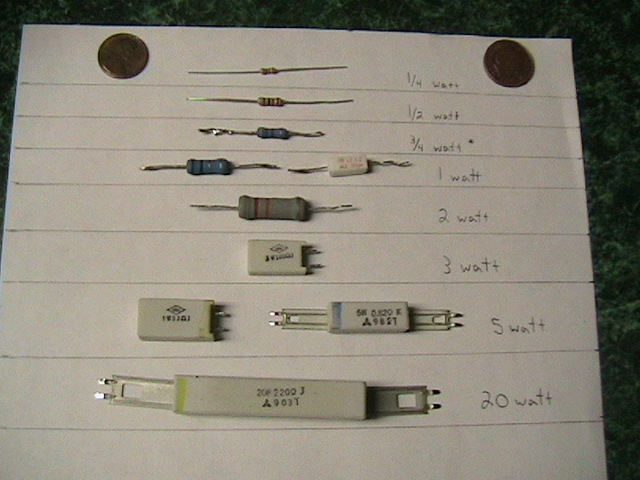
Once you know how to color code, it gets easy. The second thing resistors are rated by is their power dissipation. The higher the rating, the more heat it can dissipate in itself. Up to 1 watt resistors are common on most circuit boards. Anything higher can be found, but is not common and has a much more specific use. Click the link below to get an example of the different power ratings:
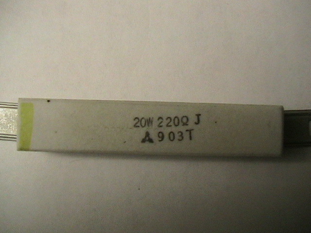
As you can see, there are many different power ratings and many different ways to make said power ratings. There are normally 10 watt resistors, but I fail to have any on me. Normally on resistors bigger than 2 watts, the actual power rating will be printed on the resistor. This is an example of a 20 watt, 220Ω resistor.
Capacitor - A capacitor is used to store a charge of electricity for various reasons. In camera's, it is used to provide the sudden voltage and current used to light a flash bulb. It can also be used to smooth out the flow of electricity in some devices, and lastly they can be used to filter. By filter, I mean they remove DC signals from AC lines (so as not to screw stuff up). There are two main ratings on a capactior; The voltage and the capacity (shown as Farads). As far as farads go, most capacitors are never 1 farad (as thats a large ammount of energy) so they are often marked with smaller divisions (such as micro or pico). 1 Farad = 1000 millifarads(mF). 1 millifarad = 1000 microfarads(µF). 1 microfarad = 1000 nanofarads(nF). And Finally 1 nanofarad = 1000 picofarads(pf). Despite all this, the standard is the microfarad (µF). This is all you need to know about capacitance for now. Just remember that 1µF is a small ammount of capacitance, while something like 10,000µF is quite large.
-Note: The funky looking character before the F in µF is called a 'mu' (pronounced mew) which is the lower case 'm' in the greek alphabet. To produce this character with your computer, generally just hold Alt and hit 0181 on the keypad while still holding alt.
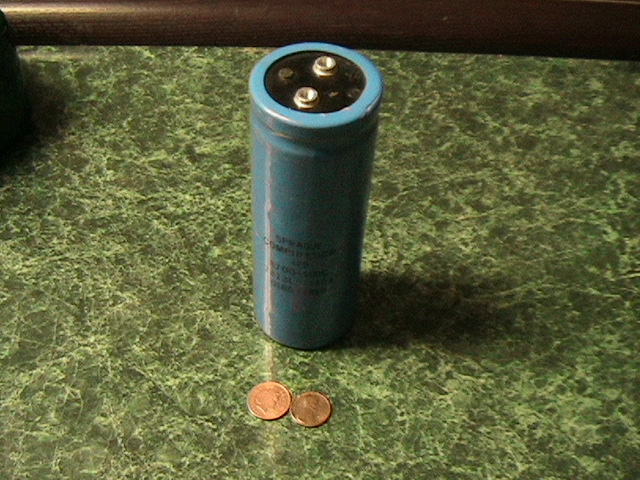
The voltage is obvious and needs little explaining. Keep one thing in mind though; don't go above the rated voltage on a capacitor as it will usually explode (to put it simply). Another thing is that size has nothing to do with the voltage rating of a capacitor. Only the capacitance is related to the size. The capacitor shown in this picture is 50v and so is the capacitor in this. The difference is that the first capacitor is 10µF while the second capacitor is 8700µF. Rarely will you find a capacitor with both a high voltage and a high capacitance. Normally the higher the voltage, the lower the capacitance.
There are two main types of capacitors - Polarised and Unpolarised. Usually polarised capacitors have a capacitance higher than 1µF, while unpolarised are less than 1µF. -As a special note, incase you didn't know already, a polarised capacitor is one which must have the positive current on one side, and negative current on the other.- Those two types can be subdivided even more, but I'll only talk about a couple. Under polarised, the only one that would concern you at this point is an Electrolytic capacitor. The values are clearly printed on the side, and so is the polarity. Kids will often mistake these as batteries, then procede to call you a nerd when you explain what it really is. Under polarised there are three that I would like you to know. Ceramic being the most important, then Epoxy, and then Metalized polyester film. These will always have low capacitances, but can have really high voltages. Metalized polyester film is usually used as a DC filter on things like computer power supplies and TVs. Epoxy capacitors are most readily found in anything with a CRT. Ceramic is the most often seen of the three. They can have almost any voltage. Below are some examples of the different types of capacitors:
Electrolytic |
Ceramic |
Epoxy |
Metalized Polyester Film |
Diodes - Diodes are probably the easiest to understand the basics of. All it does is let current flow through one way, but not the other. This is useful for preventing reverse voltage to a sensitive component. However, at some point, the current will go through eventually. The diode will tell you at what voltage and current it lets it go through both ways on the spec sheet. This is an example of a small diode.
Light-emitting diode (LED) - The title is self explanatory. These are diodes which give off light as current flows through them. Note that diodes are polarized. 99% of the time, the side with the longer leg is the positive terminal. Also, there is usually a flat spot on a side. The leg nearest the flat spot is the negative terminal. The package will usually give you a hint as to which side is which if my descriptions don't help you. Here is a great example of an LED.
Rectifier - The rectifier is a very useful componet except it only has one use; to turn AC into DC. It can't work backwards, however. It is usually a black rectangle or square with 4 legs coming out of it. Each leg is marked appropriately (Squiggles for where the AC goes in, and a plus (+) or minus (-) symbol to signify the positive and negative DC terminals). Here is a couple examples of rectifiers
IC chip - These are the little chips on the board. They can be called computer chips, or plain old "chips" but I perfer to call them IC's. IC stands for integrated circuit. Chips are basically like transistors, except there is more than 1 in a small package so it can do more complex things than just On/Off. All they basically do is control more elaborate parts. When making a device involving IC chips, it's always smart to solder in an IC socket first (make sure it's the proper size) as the heat from the soldering iron could dammage the part. Plus, if the part becomes dammaged, you have to desolder it, which is not fun as there are a lot of pins. This is a picture of a chip, and it's corresponding socket. This is actually the MAX232 chip for those who were wondering.
Transistors - A transisitor is a unique component and can be used for multiple but completely different things. It's most often used as a small amplifier, but can also be used as a switch. On a normal transistor, it has 3 connectors (which can either be two leads and the conductive case, or three leads. One lead is called the base, one is the emitter, one is the collector. I wont go into detail about these parts, since this is a basics guide. The package that the transistors come in will usually tell you which lead is the base, collector, and emitter using reference points. If it does not, you will have to look up the numbers on google, or use similar methods to deduce which lead is which. If it's connected wrong, it will destroy the transistor. There are three main types of transistors. NPN, PNP, and FET. The only one that will concern you now is NPN. By the time you are concerned about FET and PNP, you will already know about them. When soldering transistors, be very carful as heat will easily destroy them. I recommend you get good at soldering before you try to solder a transistor. When you do try, use a heat sink until you become confident with yourself.
Relay - This is a very useful part. Not as much in high voltage as it is in automotive world. It's basically an electircally powered light switch. It uses a magnet to move the switch, instead of your fingers. The magnet usually needs very little power (such as a 6volts or 12volts) but the switch can often handle up to european mains voltage (230volts). Again, if you're switching house current, make sure you go by the max voltage, not the mean. The max for North american mains is 170volts, and the max for european is 345volts. This is how you can get something like a computer to switch high power devices (for those of you who don't know, computer internals run off a max of 12 volts).
Variable Resistor - This component usually has 3 leads on it. It has a metal contact that slides over a high resistance conductor. Usually two leads are both connected to the high resistance conductor and one two the slider. When used as a simple rheostat, one wire is connected to the slider, and one to the high resistance conductor. The closer the slider to the live connector, the lower resistance. A most obvious example of this is a volume knob.
This should be all you need to know about electric components for now, just to get you through. A lot of other components (such as speakers and battery connectors) are very self explanatory.